grease trap diagram
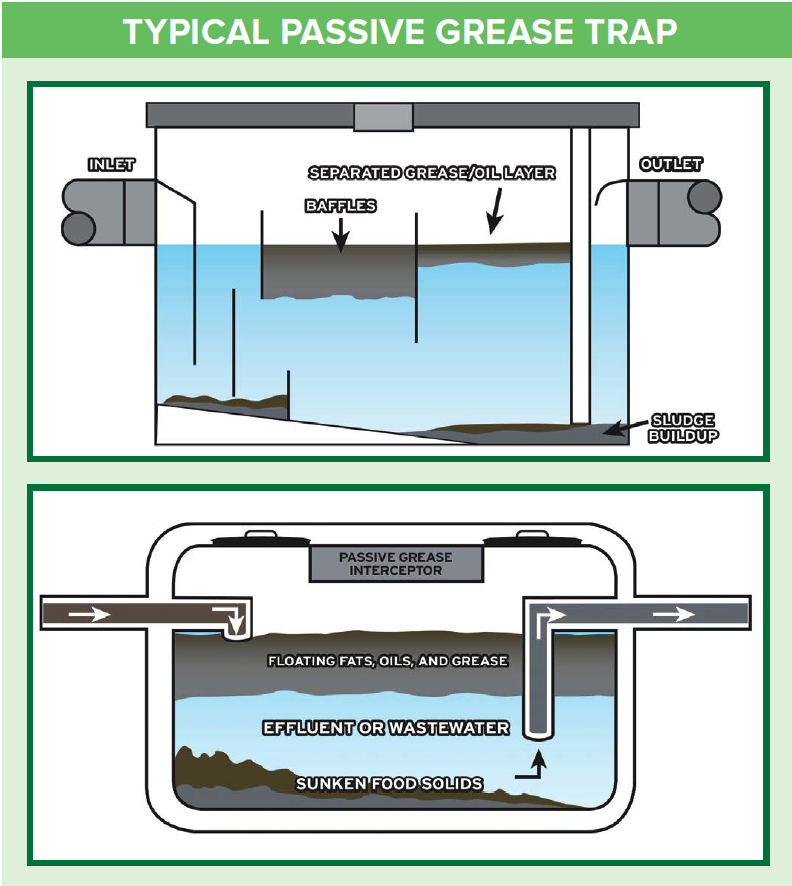
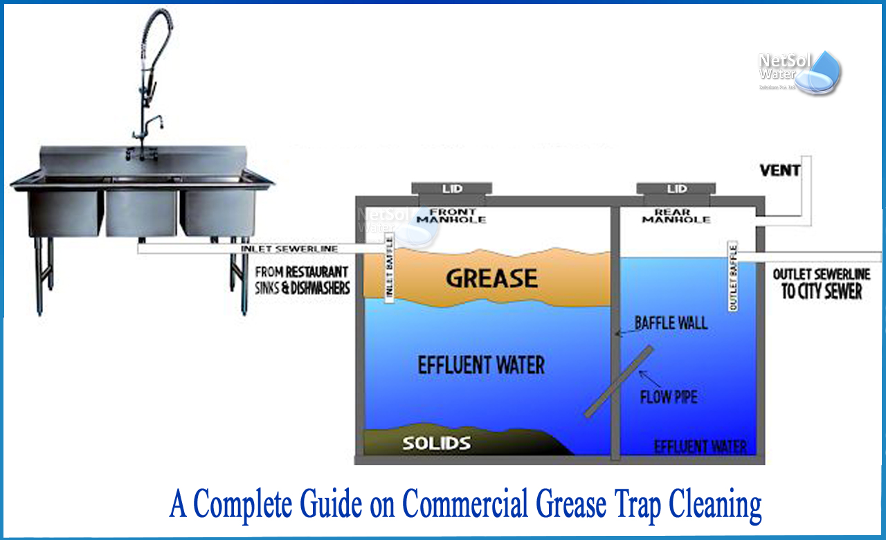
The outlet pipe has a tee that allows the internal discharge to be located within. Grease traps are designed to stop fats oils or grease from entering the sewer lines.

Grease Trap Cleaning Restaurant Grease Trap Pumping Service
Click to download files.
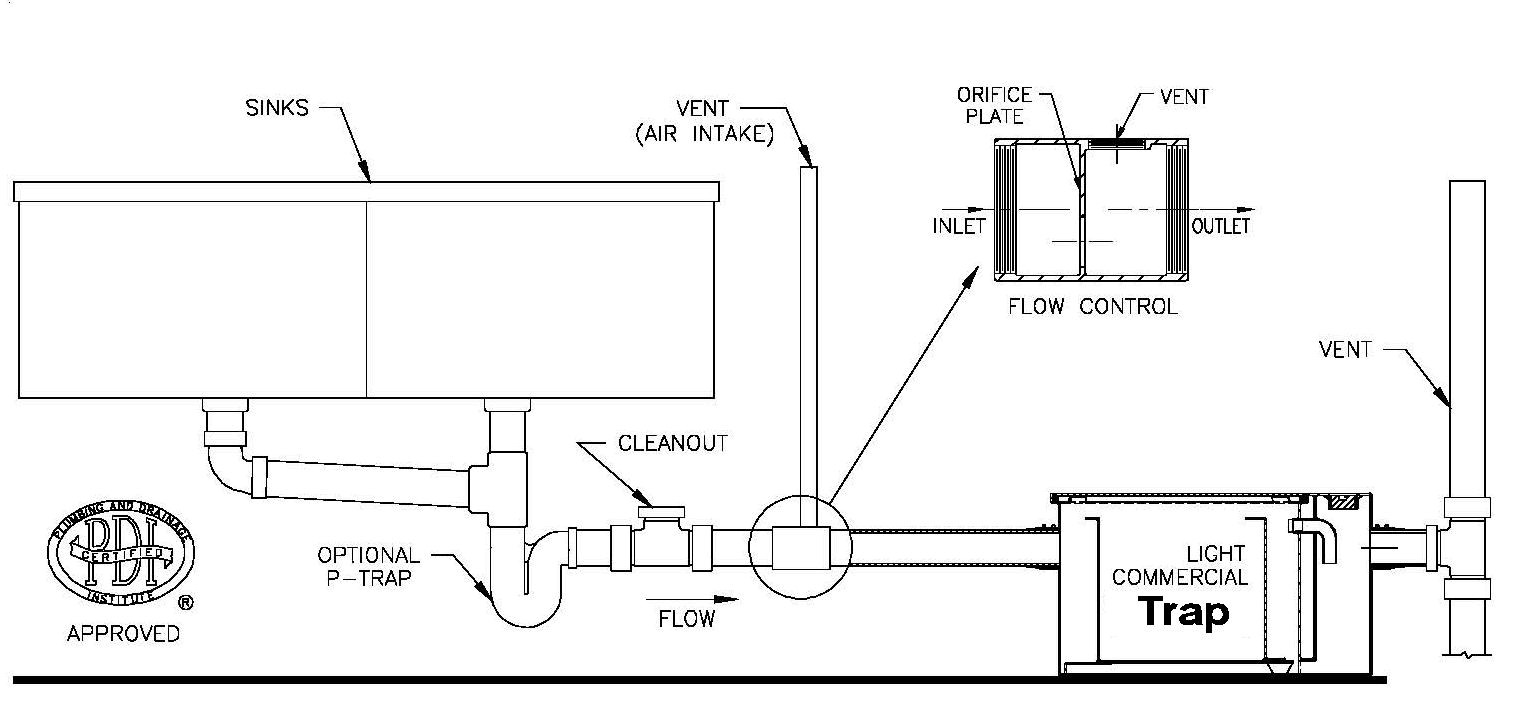
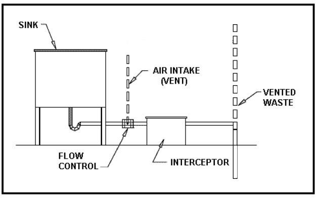
. Shipping Returns Policy. Create a grease trap diagram. FLC SERIES AppROVED SINKS OPTIONAL p _ TRAP VENT AIR.
Owning a restaurant business in Michigan requires undivided attention because of its numerous concerns. A grease trap is a device that separates grease and solids from wastewater before it enters the sanitary sewer. Water temperatures must be less than 120.
Grease trap cleaning is one of them. Internal Under the Sink Grease Trap Diagram Vent Pipe Must be lower than sink drain Flow Restrictor Grease Trap. From sinks and dishwashers to allow for adequate cooling of the wastewater.
Ensure that proper space is available for removal and periodical cleaning of the bucket which is provided to collect solid waste and. Ad Find Premium Plumbing Heating HVAC Supplies From the Biggest Brands at Low Prices. If left unchecked fats oils and grease solidifies and sticks to the insides of the pipes trapping food.
CAD Drawings for Grease Traps. 7 GPM CAD Drawings Zip file. 20 GPM CAD Drawings Zip file.
5 Best kitchen practices to improve your Grease Guardians performance quick and effective tips The key to a successful operating Grease Guardian is. Install grease trap as close as possible to the fixtures. Once youve removed the lid take note of where each part of the grease trap is located.
Browse 1000s of 2D CAD Drawings Specifications Brochures and more. Grease traps are installed as part of the plumbing at food service facilities such. Register your Big Dipper.
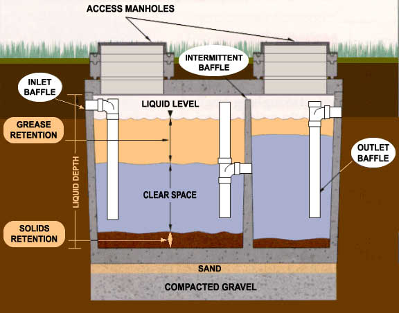
Grease traps usually consist of an underground watertight concrete tank with baffled inlet and outlet piping. Find Your Grease Trap Code. 15 GPM CAD Drawings Zip file.
Our Dedicated Team Members Are Available For All of Your Project Needs. How a Grease Trap Works see diagram following table A Flow from four or fewer kitchen fixtures enters the grease trap B An approved flow control or restricting device is installed to. Grease Trap Diagram.
Grease traps are to be installed at a minimum distance of 10 ft. 25 GPM Grease Trap CAD Drawings Zip. Creating a grease trap diagram can help you keep track of the traps.
Envirozyme Provides Controlled Grease Treatment For Traps

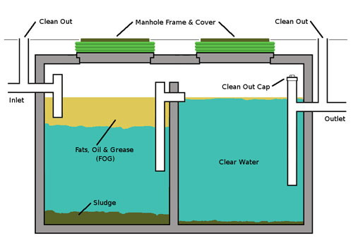
A Schematic Diagram Of A Traditional Grease Trap Two Chamber With 1 Download Scientific Diagram
![]()
Grease Trap Pumping In Holland Oh Ace Diversified Services

Grease Trap

Grease Cleanup Removal Apollo Plumbing

Sec 5 1 67 4 Grease Interceptor Standards Of Construction

Cross Section Of Typical Grease Interceptor Download Scientific Diagram
Grease Traps Interceptors Cj Deboer Engineering Septic

National Committee On Urban Pest Control Training Institute Grease Trap Grease Trap Is A Receptacle That Kitchen Wastewater Flows Through Before Entering The Sanitary Sewer Lines This Receptacle Technically Defined As
Fog Fats Oils Grease Rochester Indiana
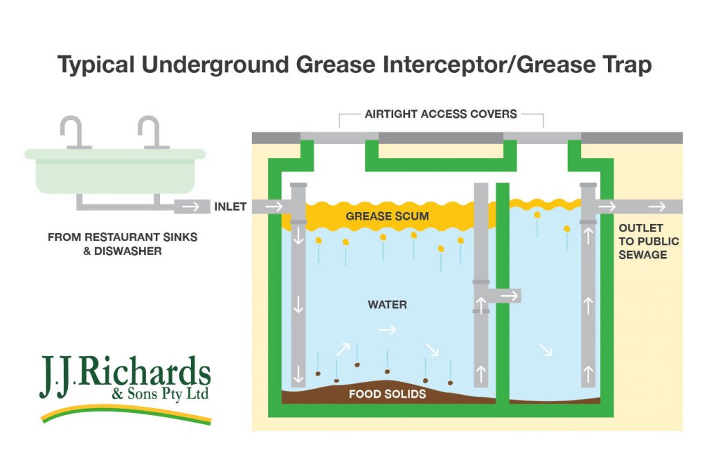
J J Richards Sons Grease Trap Cleaning Services
Grease Traps And Other Pre Treatment
Grease Trap And Interceptor Cleaning Ameriguard Maintenance Services Cooking Oil Collection And Grease Trap Management

Img Commercial Sink Plumbing Diagram Interceptor
Grease Trap 101 History Prima Supply

Grease Trap Cleaning In Des Moines Ia Interceptor Services
What Is A Commercial Grease Trap